Self-optimizing laser diode systems
In diode lasers, the gain medium is realized as a semiconductor compound with a direct band gap. In contrast to solid state laser systems like the Ti:sapphire laser, this enables direct electrical pumping of the active zone. The process of electrical pumping stimulates electrons from the valence band into the conduction band from were they can relax back into the ground state by the emission of photons, with an energy equivalent to the band gap energy. This mechanism reveals another advantage of diode lasers: by altering the composition of the active medium, the band gap energy and thereby the emission wavelength of the device can be changed. The so called “band gap engineering” is a well established technique in the semiconductor industry and allows for a huge coverage of different wavelengths with laser diodes. This spectral flexibility is an advantage compared to solid state and fibre lasers.
While in some areas, like tuneable light sources with narrow line width, laser diodes are state-of-the-art, laser diode systems are not commercially available as a light source for ultra short pulses. Theoretically, the lower boundary for pulse widths generated by laser diodes should be below 50 fs. The pulses are generated by locking the longitudinal modes of the laser cavity. The locking mechanism is realized by a saturable absorber. For this reason it is called passive mode locking. In the case of a laser diode a problem arises: the strong coupling of the real and imaginary part of the susceptibility leads to a strong wavelength chirp. This leads to a temporal broadening of the pulse and a reduction of the spectral bandwidth. This mechanism inhibits the direct generation of sub-50 fs pulses.
A first step to solve this problem was the introduction of intracavity dispersion management (IDM) by using the Fourier-external cavity laser (FTECAL) setup. The FTECAL setup is depicted in picture 1. A two section laser diode with an anti-reflection coating emits light which is spectrally diffracted by a grating. The first diffraction order is collimated by a lens while its spectral components are focused. A mirror in the Fourier plane reflects the light back into the laser diode. The zeroth order is used for output coupling. The setup is similar to a folded grating compressor, which is used for pulse compression: by moving the grating out of the focus linear chirp is generated. With a suitable alignment we were able to generate 200 fs pulses with the usage of an external pulse compressor. However, moving the grating out of the focus will always introduce a slight spatial chirp, which has a negative influence of the pulse generation.
")
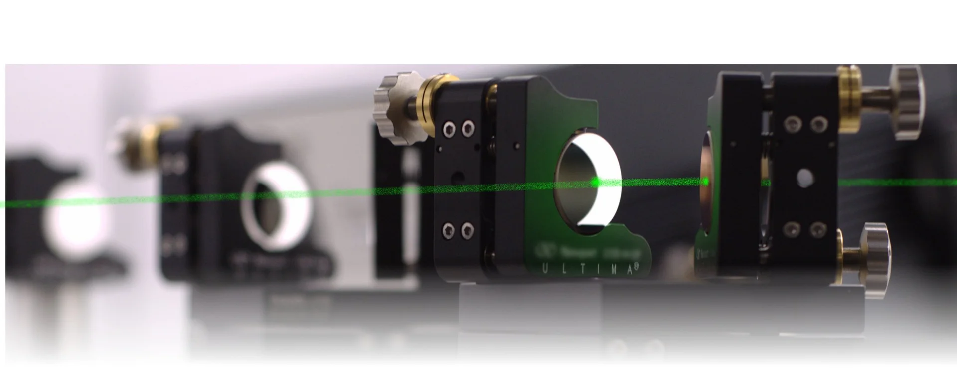
Fig. 1: FTECAL setup with double mask SLM in the Fourier plane
In order to avoid this problem we are trying in the scope of a project (funded by the Deutsche Forschungsgemeinschaft) to compensate the wavelength chirp with a spatial light modulator (SLM). This has the advantage compared to the previous approach, that we are able to compensate arbitrary chirp while avoiding problems due to spatial chirp. In addition, the SLM allows the manipulation of the spectral amplitude. The SLM is controlled by an evolutionary algorithm which optimizes the laser systems on parameters like shortest pulse width and highest spectral bandwidth. We aim to generate sub-100 fs pulses with this approach.
Another field of application is the use of the system in a terahertz (THz) time domain spectrometer, which can be used for spectroscopic applications in the region from 100 GHz up to several THz or for material testing. The most important feature here is the pulse width, because it is directly proportional to the bandwidth of the THz system. The use of a laser diode system has the potential to significantly reduce the costs for THz systems. In addition, the shaping of the optical spectrum could lead to highlighting of selected areas of the THz spectrum. This would lead to a higher flexibility in contrast to commercial laser systems.
Reference:
- [1] M. A. Alloush, R. H. Pilny, C. Brenner, A. Klehr, A. Knigge, G. Tränkle, and M. R. Hofmann, “Passive, active, and hybrid mode-locking in a self-optimized ultrafast diode lase”, SPIE 10553, Novel In-Plane Semiconductor Lasers XVII, 105530N (2018)
- [2] R. H. Pilny, B. Döpke, J. C. Balzer, C. Brenner, A. Klehr, A. Knigge, G. Tränkle, and M. R. Hofmann, “Femtosecond semiconductor laser system with resonator-internal dispersion adaptation”, Optics Letters, Volu-me 42, Issue 8, pp. 1524-1527 (2017)
- [3] R. H. Pilny, B. Döpke, J. C. Balzer, C. Brenner, A. Klehr, G. Erbert, G. Tränkle, and M. R. Hofmann, “Interaction of phase and amplitude shaping in an external cavity semiconductor laser” - SPIE 9767, Novel In-Plane Semiconductor Lasers XV, 97670O (2016)
- [4] R. H. Pilny, B. Döpke, C. Brenner, J. C. Balzer, and M. R. Hofmann, “Optimization of a mode-locked diode laser by manipulation of intracavity dispersion and absorption with an evolutionary algorithm”, R. H. Pilny, B. Döpke, C. Brenner, J. C. Balzer, and M. R. Hofmann, CLEO Europe (2015)
- [5] J. C. Balzer, R. H. Pilny, B. Döpke, A. Klehr, G. Erbert, G. Tränkle, C. Brenner, M. R. Hofmann, “Passively Mode-Locked Diode Laser With Optimized Dispersion Management”, IEEE STQE, Volume 21, Issue 6, 1101008 (2015)
- [6] B. Döpke, R. H. Pilny, C. Brenner, A. Klehr, G. Erbert, G. Tränkle, J. C. Balzer, and M. R. Hofmann, “Self-optimizing femtosecond semiconductor laser”, Optics Express Vol. 23, Issue 8, pp. 9710-9716 (2015)
- [7] B. Döpke, J. C. Balzer, R. H. Pilny, C. Brenner, A. Klehr, G. Erbert, G. Tränkle, M. R. Hofmann, “Ultrashort pulse generation with semiconductor lasers using intracavity phase- and amplitude pulse shaping”, SPIE 9382, Novel In-Plane Semiconductor Lasers XIV, 93820D (2015)
- [8] J. C. Balzer, B. Döpke, C. Brenner, A. Klehr, G. Erbert, G. Tränkle, and M. R. Hofmann, “Mode-locked semiconductor laser system with intracavity spatial light modulator for linear and nonlinear dispersion management”, Optics Express Vol. 22, Issue 15, pp. 18093-18100 (2014)
- [9] J. C. Balzer, B. Döpke, A. Klehr, G. Erbert, G. Tränkle, M. R. Hofmann, Femtosecond semiconductor laser system with arbitrary intracavity phase and amplitude manipulation, SPIE 9002, Novel In-Plane Semiconductor Lasers XIII, 90020D (2014)
Colleagues: